Magneti Marelli Selespeed CFC328 (DUALOGIC): Italian robot
To refer to this type of transmission here in Russia we use the term “robot”. Professionals use the abbreviation МТА, which is the same in Russian and in English: “Механическая Трансмиссия Автоматизированная”, “Mechanical Transmission Automatized”. This gearbox was originally designed as a purely manual transmission and then complemented with an “automated” unit. We have every reason to call it “robot”, because it’s exactly this transmission that works for the hands and feet of the driver: turns the clutch on and off, shifts the gears up and down. “Robots” are produced by such world-famous manufacturers as ZF, Magneti Marelli, Getrag. The main differences between these models are based on the drive type used inside this unit - an electrical or a hydraulic one. The hydraulic drive has one big advantage - speed-of-response. It shifts gears much faster than solely electrical “robots”. This is a favourite type of control for actual racing cars and ... real Italian cars. The temperament of a southern nation simply could not have chosen any other robotic transmission.
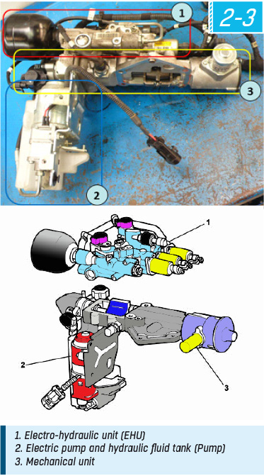
The Selespeed CFC328 is produced by Magneti Marelli, an affiliated company that belongs to the FCA. Basically, it’s a “robot” of an electrical(1)-hydraulic(2) type, installed on the mechanical(3) C514 gearbox.
Diagnostic trouble codes
Troubles connected with this МТА can be divided into three groups - let us denote them with Roman numbers for convenience:
I electrical;
II hydraulic;
III mechanical.
For the driver, all МТА troubles always look the same: the dashboard icon (значок)* goes on, a buzzer sounds, and on models with a matrix display a scrolling text appears stating the name of the failure. The user’s manual in each and every case recommends to consult car service center professionals immediately.
We can also discern three different patterns of the vehicle’s behaviour:
А sporadically incorrect gear shifting;
В failure to shift all gears or to shift into third gear and up;
С activation of the emergency mode of the МТА after intensive use or brake application.
When considering the diagnostic trouble codes, we will be assigning them indices, combining the abovementioned numbers of the group of troubles and letters of the vehicle’s behaviour. For instance, the DTC P1760 will have the index С-I (the МТА gets into emergency mode – C, the cause is electrical – I), so we will be referring to it as P1760(C-I)
During “the unbelievable adventures of Italians in Russia” /an allusion to a comedy of the Soviet times/ (the observation period - 2006 to 2014 - is quite short) I repeatedly encountered about a dozen MTA DTCs, but some of them have a wide range of causes and, consequently, a variety of repair methods.
List of common DTCs
(for some trouble codes we preserve the original spelling for the poor Russian translations of the original diagnostic tool Examiner)
P1760 – Brake Switch
P0571 – Service Brake Switch (from CAN)
P1741 – Clutch Position Sensor
P1742 – Multi-position Sensor (range sensor)
P1743 – Clutch Plate Sensor
P1769 – Pilot Pump Relay Switch Is Stuck (Pilot Relay)
P1810 – Incorrect Clutch Work at gear shifting
Р1773 – Hydraulic Circuit Pressure
P1744 – Hydraulic Circuit Pressure Sensor
С0060 – ECU Failure (Microchip)
P1818 – Gear Shifting Control
Important warning: You can only take Italian MTAs for repair if you have an original FCA diagnostic tool (Examiner or WiTech), or a device that can do the complete procedure package for MTA adjustment and diagnostic. After each procedure in which you removed and/or disassembled any MTA units, you need to perform bleeding, calibration and self-adjustment procedures.
MTA removal and disassembly Selespeed CFC328
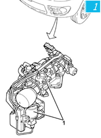
Removing a “robot” presents no difficulties. The standard time limit for this type of work is 1.2 hours. To do it, you needn’t take down the transmission itself. You only need to carefully disconnect the electrical wiring, the “ground”, unscrew 10 bolts – and the MTA is set free. The official manual recommends to take it out from the bottom of the vehicle (1), as if going round the transmission counterclockwise, but if you first remove the units that stand in the way, you can take out the whole MTA assembly (2) from the top, without using a lift (3).
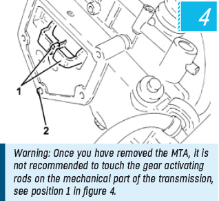
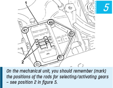
Warning: After removing a “robot”, it is not recommended to touch the gear rods on the transmission (5), and you should remember or mark the position of the mechanism selecting (4) and activating gears on the mechanical unit of the “robot”. As a default, it is a neutral position.
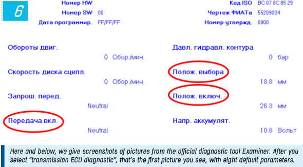
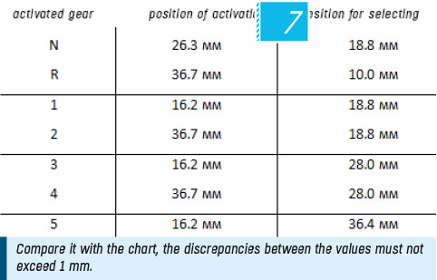
The assembled unit will work correctly only if the mechanisms are installed in the right positions. You can assemble it with the wrong positions of the rods and their responding parts, but after such incorrect assembly it’s hard to tell right away why there’s no self-calibration. I this case, the self-diagnostic performed by the diagnostic tool will end with the DTC 00 (automatic calibration not performed). Diagnostic technicians start blaming all kinds of things except for the incorrect positioning of mechanisms at assembly. In order to make sure that the unit is installed in the wrong way, you need to look at the readings of the two position sensors in mm (6) using a diagnostic tool - the discrepancies between those readings and the tabular figures (7) when shifting into each gear must not exceed 1 mm.
Common DTCs
P1760(C-I) and P0571(C-I) (Brake Switch and Service Brake Switch (from CAN)
If these DTCs appear separately (which doesn’t often occur), the repair comes down to checking the position sensor (switch) of the brake pedal by observing its position (on/off) in the NBC unit (Body computer). You need to carefully remove the sensor, check it (replace it if needed) and click it back in its place. If that doesn’t help, also check for corroded connectors and the condition of the wiring in general.
If these DTCs appear together (which is often the case), you need to reprogram the МТА control unit.
P1743 and P1810(A-I and A- III) Clutch Position Sensor and Incorrect Clutch Work at gear shifting (if they appear simultaneously)
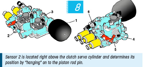
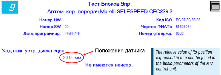
The sensor is located on the electro-hydraulic unit (position 2) (8) right above the clutch servo cylinder, and controls its travel, “hanging” on to the piston rod plunger. The relative value of its position, expressed in mm, can be found in the basic parameters of the transmission’s control unit (9).
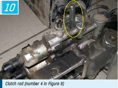
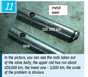
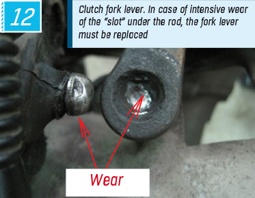
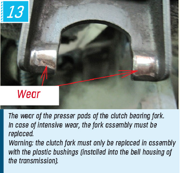
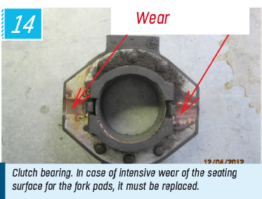
The given figure – about 21 mm – is critical. A mm give or take (from 19 to 22 mm) means that the clutch unit is fine. If the figure is outside this range though, you need to search for the cause of the discrepancy. Consequently, the ECU of the “robot” gives the same DTC - P1743. It’s possible to say that the value discrepancy is accumulated due to the wear of the mechanical parts of the clutch drive unit, the clutch actuating rod (10) (11) and the driving lever of the clutch fork (12). Besides, the presser pads of the clutch bearing fork (13) wear too, as well as the clutch bearing itself (14). In case of intensive wear, the whole fork must be replaced, and it makes sense to replace the bearing as part of the clutch assembly.
This failure often has an electrical nature, so you need to check the wiring, the connectors and the sensor itself.
C0060(A-I and A- III) ECU Failure (Microchip)
Manifests itself in the absence of connection to the diagnostic tool or provision of knowingly false parameter values (15) in response to the request of the diagnostic tool.
In my opinion, this is the most treacherous DTC for a “robot”, because it can have a variety of causes - electrical or mechanical, like the previous DTC P1743.

As for the electrical part of the DTC, you can diagnose by touch the excessive heat of the transmission control unit. The ECU itself is located in the car’s interior, at the front passenger’s feet, and is covered with a plastic feet rest (it’s located under the floor mat and is fixed with two bolts). It is necessary to check all the ground points on the car body and the engine - especially those ones that are hidden underneath the front right-hand body pillar. There are a few of them, and usually an electrician, after checking the top ground point, puts his mind at rest – and then ends up checking the rest of the ground points after going through “all the circles of hell” of blind diagnostic. Also, you should check the connectors and the overall condition of the harness, as well as the power supply in the unit. If no other causes are identified, the next step will be to replace the ECU of the “robot”. But… this is only if we are sure that this is not the case of the biggest “treachery of a robot” – the mechanical nature of the DTC С0060. (Paradox? Unfortunately, not.)
What can be the cause of the knowingly false parameter values?
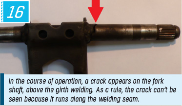
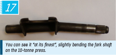
The right answer is: the clutch bearing fork. It has been observed that with the clutch, the “robot” with a hydraulic drive works more harshly and quickly - that’s the basis of its speed-of-response and the main advantage over other types of “robots”. But the fork is subjected to torsion impact. The maximum pressure concentrates at the place where the fork is located, because this spot is weakened by girth welding (red arrow) (16). In the course of operation, when the vehicle has run about 40–60 thousand kilometers in a big city, a crack appears on the fork shaft - right above the welding, to be exact. As a rule, it’s hard to see because it runs along the welding seam, but you can see it if you slightly bend the fork shaft on the press (17).
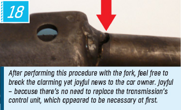
After performing this procedure with the fork, feel free to break the alarming (18) yet joyful news to the car owner. Joyful – because there’s no need to replace the transmission’s ECU.
P1810(A/B- II/III) Incorrect Clutch Work at gear shifting (when it appears)
In case of this DTC, the first step is usually to replace the clutch. However, if the mileage is not very big (under 30,000 km), in some cases the clutch calibration with a diagnostic tool is a great solution (basically, it’s the correction of the friction plate wear index).
Recommendations for replacing the clutch assembly Selespeed CFC328:
Since the patterns of work of a “robot” are less perfect, than those of a trained - as it “thinks” - human body, the wear of a traditional one-plate dry clutch in an МТА occurs twice as often as in the case of a manual transmission. Which means, that by the time the vehicle has run 60-80 thousand km in a big city, the clutch plate is usually badly worn and needs replacement. There is a test in the Examiner called “Calculating the clutch wear index”. This index is used by the ECU for internal operation. For its visualization, you need to perform a driving test, that is to drive the vehicle for about 500 m following the recommendations of the device. So, the car needs to run and you need quite a long straight road. The index is expressed in some conditional units (they have no name, the values can be both negative and positive). The range of this index isn’t specified in the manufacturer’s technical literature and was determined experimentally. A new clutch plate has the index -3000 ÷ -2000, whereas a plate that needs urgent replacement has the index 9000÷10 000, so the scale length is 12000 units. At the vehicle’s mileage specified above, the value after performing this test is normally 6000–7000 units, which means that the clutch wear is 70–80%, and its replacement is a must. By this time, incidentally, our “treacherous” clutch bearing fork can be ready for replacement as well. One more thing - at such wear, when shifting into top gears (4th or 5th), there can occur the knocking-out of the gear in motion, which is not particularly pleasant. So, we can draw a simple conclusion: if vehicles of the FCA group equipped with an МТА have run 60–80 thousand km in a big city - don’t hesitate to replace the clutch assembly along with the fork and the plastic bushings. Comfort has to be paid for - either right away, at the initial stage (when you buy a more expensive classic automatic transmission) or eventually, by deferred payments (if you opted for a cheaper robotic transmission).
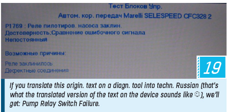
P1769 (B- II) – Relay Sw. of Pilot P-mp is Stuck
If you translate this origin. text on a diagn. tool into techn. Russian (that’s what the translated version of the text on the device sounds like ) you will get something like: Pump Relay Switch Failure (19).
The source of energy for a “robot” of this type is service fluid under high pressure supplied by an electrical pump – a gear-type pump driven by an electric motor, which is controlled by a basic relay switch. The latter is called a cryptic name “pilot relay”.
Obviously, this DTC indicates troubles not only in the relay switch. It is quite reliable by itself, and its breakdown in most cases is caused by a string of failures: service fluid leakage (the causes of power fluid leaks will be covered later) – filling the “robot” in the nearest garage with something that only vaguely resembles service fluid (and brake fluid looks exactly like service fluid, for instance) - pressure accumulator fault – frequent and short-term activations of the pump electric motor – burnt relay.
However, the transmission troubleshooting in case of this DTC needs to be done in the usual - “classical” - way. You need to check:
- the pump fuse switch and the position of the relay switch;
- the connectors and the condition of the wiring;
- the winding insulation of the electric motor.
If everything is fine, replace the pilot relay and start searching for the root cause of the trouble.
Check the type of service fluid the “robot” is filled with, it must be TUTELA CAR CS SPEED only! Unfortunately, in all user’s manuals we can read the following kind of definition for this service fluid: SPECIAL ADDITIVE OIL OF THE ATF DEXTRON III TYPE. In Russia, it is believed that the phrase “of a particular type” gives grounds for using this exact type - in our case it’s ATF DEXTRON III. The Italian MTA does work on Dextron, of course, but not the way the product engineers pictured it: gear shifting is harsher, especially in cold seasons. As for the brake fluid, which is similar to the original service fluid in its look and consistency, our МТА doesn’t work - it literally dies (the brake fluid eats through the seals in the hydraulic circuit).
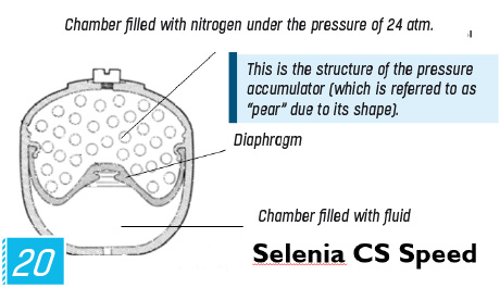
In “garage-type” service centers they can fill your transmission with something liquid that can ruin the pressure accumulator (20), which is referred to as “pear” due to its shape.When the diaphragm is ruined, the “pear” ceases to work, that is accumulates pressure without activating the pump. Under normal conditions, when at each engagement of the “robot” the pressure is reduced gradually (21), the pump turns on at some intervals, and has the time to cool down between the working cycles. If the “pear” is leaky inside, the pump turns on at each gear shifting and gets overheated, which can even lead to the burnt winding, or, in the best-case scenario, the burnt pilot relay. Being a source of trouble, the pressure accumulator is easily replaceable, and after that the normal functioning of the “robot” is restored. The burnt motor, if wished, can be rewound in the same car shops where starters get rewound.

Р1773(А-II) Hydraulic Circuit Pressure
This unpleasant DTC can indicate a wide variety of troubles, from the replacement of the hydraulic part of the “robot” in assembly (due to the inner overflow of the service fluid) to its downright leakage.
In most cases, the latter is the real cause: there’s no service fluid – so the “robot” can’t work properly.
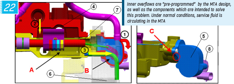
Inner leaks are “pre-programmed” by the very design of the МТА and are shown with yellow arrows in Figure (22), but so are the components that are meant to solve this problem: chamber А, tube 3, connecting А to operating tank 6. Under normal conditions, service fluid is circulating in the МТА: at momentary pressure supply to clutch pistons 2 and to two-way piston 4 for selecting a gear, insignificant leaks occur (directly proportional to the short time of the piston work), which drain into the tank through chamber А and tube 3. That’s its normal operation.
What happens during the cold season? Two factors start producing their impact: the Russian user’s mentality and low temperatures, both aggravating each other.
Let’s consider it in detail.
When really cold temperatures set in (-20 C and below), and even during the warm season, the driver starts following the pattern: start the engine, get out of the car and then - there are options - have a smoke, shovel the snow, go round the car, thumping on all the four wheels, etc., with only one goal: to warm up the car. Anyway, the client violates the manufacturer’s recommendation: “You shouldn’t warm up the engine when the vehicle is parked…”, stated in the User’s Manual. Usually it only affects the engine lifespan and the overall fuel consumption. In cars equipped with an МТА, however, it can lead to the following: after starting the engine, the control unit of the МТА “prepares” for immediate breakaway and releases the clutch (which does make sense!), but this may not happen for another 10 minutes. Which means that for quite a long time piston 2 is under pressure, the leaks into chamber А are great (proportional to the time, besides there’s a factor of the loss of elasticity of the piston seals because the engine is still cold). The service fluid is accumulated in chamber А, due to its high viscosity and great volume it can’t all get drained through tube 3 and flows into chamber В of the rod position sensor case 5, there it reaches the level of breather С – an orifice with a diameter of 1.8 mm – and leaks outside. As a result, the MTA’s operative parts run out of service fluid – the vehicle ceases to respond to commands.
Fortunately, filling the transmission with the correct (!) service fluid brings back the lost operability.
What is to be done?
Change the driving pattern: starting the engine means that you drive right away. Another option is to put the МТА operating lever into N (otherwise, as a default, 1st gear is activated and the clutch is released).
Ways to eliminate the problem:
1. Reducing the leakage through clutch control piston 2, which is the main leakage point, since the original seal is definitely not made from winter tyres. You can learn how to deal with this problem on the website of the journal in the presentation “МТА – replacement of service seals in the valve body”.
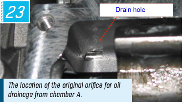
2. Improving the original oil drainage from chamber А through the connection hose and tube 3.
The improvement of drainage can be achieved by means of enlarging the Drain hole (23) along with the replacement of the connection hose for a handmade one of a bigger diameter and using a corresponding return pipe - so, it is possible to enlarge it up to 6–8 mm. It is also necessary to enlarge the connection hose on the service fluid tank.
Р1818 (A/B-III) Shifting Gears Control (24)
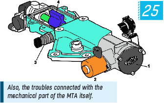
This DTC can be called Et cetera: when the ECU can’t discern a plausible cause of the trouble, it gives out this DTC. It also includes all kinds of transmission troubles (synchronizers fallen to pieces, shattered gears, etc.) and mechanical issues of the “robot” itself (25).
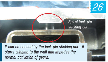
One of the probable causes of this failure is the abnormal work of solenoid №2 (jamming, seizing, the breakdown of the case, the looseness of the base plate, etc.). It is necessary to check the solenoid, pulling it out without removing the “robot”. Don’t forget to rivet its heading on the diamond-shaped base plate. Also, the locating pin return spring weakens (it can be stretched for 3–4 mm). Another reason is the lock pin sticking out at a weird angle (26), which starts clinging to the wall impeding the normal activation of gears.
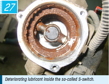
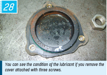
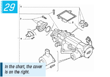
Eventually, when the car is mostly parked, for instance under the snow, the DTC P1818 is mostly caused by the deteriorating lubricant (27) in the unit of the so-called S-switch 1, which can be accessed after removing the cover fixed with three screws (28).
You can try changing the lubricant, but in this case, a complete disassembly of the unit will be needed, which sometimes can’t be done. Then it makes sense to replace actuator 6, since it is delivered separately (29).

Final operations after each repair
After any replacement or repair works in which the “robot” or its parts were dismantled, it is necessary to perform a number of procedures with a diagnostic tool.
Here is their complete list:
- clutch bleeding;
- pressure release in the accumulator;
- enabling the clutch self-calibration;
- self-calibration after coming off the production line;
- self-calibration after service or repair works;
- new actuating devices;
- calculation of the clutch wear index;
- deletion of statistical data;
- re-recordering of the data into the control unit.
Before removing the “robot” you need to release the pressure in the accumulator. After the final assembly – perform the clutch bleeding (which means - bleeding of the whole system). It is recommended to do it repeatedly. The good news is that it is all about pressing buttons – you needn’t open any connection hoses.
And now I’m going to say strange things. It may sound absurd, but these recommendations come from first-hand experience, and it is exactly after these procedures that MTAs function better, rather than if you follow the recommendations from the manufacturer’s manual (performing each procedure only once).
I call it the “pyramid rule”:
- the first operation “statistical data deletion”: is to be performed once;
- the second operation “clutch self-calibration enable” is to be performed twice;
- the third operation “service self-calibration” is to be performed three times.
Those are mandatory operations and a mandatory sequence with a little altered number of repetitions. Healthy superstitions have never harmed real professionals. A “robot” is an enigmatic thing, like any real automatic transmission!
Alexey Kholodov